

Views: 0 Author: Site Editor Publish Time: 2026-07-15 Origin: Site
Uneven tire wear, a crooked steering wheel, or a car that drifts after suspension work can make DIY alignment seem like a simple measuring job. In practice, accurate results depend on more than adjusting tie rods: the vehicle must be mechanically sound, the floor level, and every tool mounted against a stable reference.
Choosing the right equipment—and using a Car Wheel Alignment Clamp correctly—helps separate real alignment errors from bad readings. The sections ahead cover tool selection, setup, adjustment order, and the checks that confirm whether the final measurements can be trusted.
Alignment cannot compensate for worn steering or suspension parts. Before fitting a Car Wheel Alignment Clamp, inspect the tie-rod ends, ball joints, control-arm bushings, wheel bearings, wheels, and tires for looseness or damage. A loose joint lets the wheel move after measurement, while a bent rim changes the clamp’s reference. A complete pre-alignment inspection should cover the wheels, tires, steering linkage, and suspension components before any adjustment begins.
Repair failed parts first and check for mismatched tires, seized adjusters, or damaged threads. Otherwise, readings may keep changing even when the equipment appears secure.
Use specifications for the exact vehicle, suspension, drivetrain, and load condition rather than copying a generic target. Preferred toe, camber, and caster values can vary between models and configurations. Set cold tire pressure to the placard or owner’s manual figure, not the maximum pressure molded into the tire sidewall. Complete ride-height changes first, then establish the specified fuel level, cargo, or ballast.
Check the floor at all four tire positions with a long level or digital inclinometer. Side-to-side slope can distort camber, while front-to-rear slope can influence a caster sweep, so use firm, measured pads where necessary. Center and secure the steering wheel, roll the car into position, and settle the suspension consistently. Setup errors caused by an uneven surface or moving steering wheel can easily resemble genuine alignment changes.
Scribed tire lines, a fine tape, toe plates, or parallel strings can support a front-toe check. Matching front and rear points reveal toe-in or toe-out, but both readings must be taken at the same height and compared with vehicle-specific limits. A two-point method usually shows total toe only, while squared strings provide a center reference for measuring each wheel separately.
DIY task | Useful equipment | Information obtained |
Quick front-toe check | Scribed lines and fine tape | Approximate total toe |
Individual-wheel toe setup | Squared strings, steel rule, slip plates | Toe at each wheel |
Toe, camber, and caster work | Gauges or electronic heads, clamps, turn plates | Multiple alignment angles |
Camber requires a gauge, inclinometer, or electronic head referenced to vertical. Caster normally uses a controlled steering sweep, making turn plates or another wheel-angle reference necessary. Slip plates prevent tire bind during tie-rod adjustment. A steering wheel holder, wheel chocks, suitable wrenches, and torque wrench complete the setup; corner-weight and bump-steer tools are outside normal home alignment work.
A Car Wheel Alignment Clamp does not calculate or correct an angle by itself. It holds a target, sensor, electronic head, or gauge in a repeatable relationship with the wheel:
wheel → clamp → measuring device → reading
Uneven contact near the beginning of that chain can make a precise sensor report the wrong position.
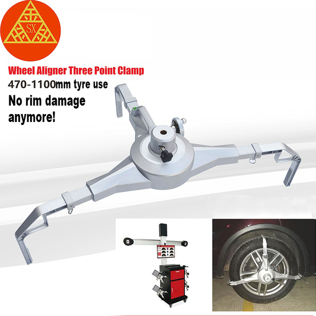
Fitment should be checked by rim size, profile, target-hole diameter, contact style, and alignment-system compatibility. The Universal Wheel Alignment Head Clamp for Pick-up accommodates rims from 11 to 25 inches and is available with Φ15, Φ16, or Φ18 mm target holes. Its accumulative tolerance is no greater than 0.20 mm, and its removable rim fingers support different wheel and tire contact requirements.
The 10-inch Electronic Wheel Alignment Quick Clamp also accommodates rims from 11 to 25 inches and accepts the same target-hole sizes. Extension arms expand its application to tires with diameters from 720 to 1,180 mm. These dimensions provide a useful starting point, but wheel clearance and measuring-head compatibility should still be confirmed before using the Car Wheel Alignment Clamp.
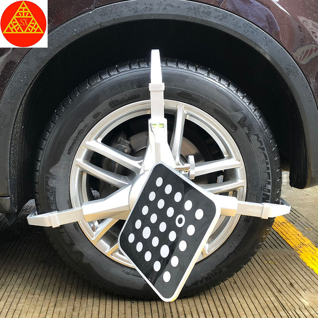
Clean the wheel where the Car Wheel Alignment Clamp will make contact, then inspect the fingers, rods, blocks, and locking points. Dirt, wheel-weight interference, a damaged rim edge, or contact with the tire sidewall can tilt the clamp before the measuring head is installed. Position it symmetrically and tighten it in a balanced sequence rather than loading one contact point fully before the others.
Seat the target or sensor completely and engage the locking pin without forcing the assembly sideways. Removable rim fingers help adapt the interface to different wheel constructions, but every contact point must still share the load evenly.
Gently test the mounted wheel alignment clamp for movement without using the sensor as a handle. When the displayed angle changes after the assembly is touched lightly, correct the Car Wheel Alignment Clamp mounting before zeroing the system. Repeated readings from a moving reference only repeat the same error.
Even an undamaged wheel can have a small amount of rim runout. Because a Car Wheel Alignment Clamp follows the wheel surface, many electronic alignment procedures use rolling or raised-wheel compensation to separate mounting variation from the actual alignment angle. Complete the required compensation procedure and avoid repositioning the Car Wheel Alignment Clamp afterward.
Place the steer wheels on turn plates or low-friction slip plates. Free movement prevents tread bind during toe adjustment and supports a controlled caster sweep. Keep the steering wheel centered and locked for toe work, adjusting the holder as required when the wheels must turn during caster measurement.
After each adjustment, roll the vehicle backward and forward and settle it in the same way. Use a consistent sequence:
mount → compensate → measure → adjust → settle → remeasure
Consistency matters more than collecting multiple readings from an unstable setup.
Begin with the specified caster target and the steering sweep required by the measuring device. Turn-plate markings provide a dependable wheel-angle reference; steering-wheel position alone is not precise enough because steering ratios and free play vary between vehicles. Adjust caster only through approved points such as shims, eccentrics, control-arm positions, strut mounts, or strut rods.
Not every road car includes a normal caster adjustment. When the value is outside tolerance, inspect ride height, bushings, mounting points, and structural components instead of improvising a correction.
Return the steering to center and confirm that each Car Wheel Alignment Clamp remains secure. Use the same contact plane and calibration method on both wheels, then make small changes at the approved camber adjuster. Compare each side with the preferred value, allowable tolerance, and permitted cross-camber difference rather than correcting the vehicle solely by road feel.
Changing camber often shifts toe because the wheel and steering arm move with the suspension. Finish camber before trying to perfect toe. Following the sequence of caster, camber, steering-wheel centering, and toe reduces repeated measurements and unnecessary readjustment.
Total toe describes the combined relationship of both wheels on an axle. Individual toe shows how each wheel sits relative to the vehicle centerline or thrust direction. Balancing the individual values helps keep the steering gear and steering wheel centered while the vehicle travels straight.
Record the starting readings and mark both tie-rod positions. Loosen the locknuts, move the adjusters in small increments, and track the effect on each side. When a Car Wheel Alignment Clamp supports an electronic head, pause the procedure if the clamp shifts while nearby hardware is being handled.
Correcting the entire error through one tie rod may put total toe inside tolerance while leaving the steering wheel crooked. Divide the correction according to the initial left and right readings, keep the steering wheel holder fixed at center, and work toward the exact target specified for the vehicle.
Hold each adjuster while tightening its locknut so the tie rod does not rotate away from the selected position. Use the manufacturer’s torque procedure for every loosened fastener. Record the measurements before and after adjustment so that movement during tightening can be identified immediately.
Roll the car, settle the suspension, and take a complete new set of readings. Confirm camber where its adjusters were disturbed, then check individual toe, total toe, and steering-wheel center. Continue until consecutive measurements agree rather than stopping as soon as one reading enters the acceptable range.
Record the final angles, tire pressures, floor setup, and vehicle load. These notes provide a baseline for monitoring tire wear and make the next Car Wheel Alignment Clamp setup faster.
Take at least two final measurement sets after rolling and settling the vehicle. Remove and reinstall one Car Wheel Alignment Clamp, repeat any required compensation, and check whether the value returns close to the recorded figure. A large difference points to contact position, rim runout, loose hardware, floor slope, or compensation error rather than a suspension setting.
Compare the left and right values as well as the totals. Watch for changes after locknuts are tightened, the steering holder is released, or a wheel is turned and returned to center. A credible Car Wheel Alignment Clamp setup should survive these checks without requiring the operator to search for the previous reading.
Choose a safe route and begin at low speed. Check steering-wheel position, straight-line tracking, steering return, and any new noise or looseness. Road feel cannot replace measured geometry because road crown, tire construction, unequal wear, brake drag, or damaged parts can create a pull even when static angles are within specification.
Inspect the tread over the following weeks for renewed feathering or shoulder wear. Correct tire pressure and alignment help preserve tread life, while continuing irregular wear calls for further diagnosis.
Stop when the Car Wheel Alignment Clamp cannot be mounted securely, readings will not repeat, an adjuster is seized, or the correct adjustment procedure is unavailable. Structural damage, large unexplained side-to-side differences, or persistent pulling after stable measurements also justify professional diagnosis. Further adjustment by feel can hide the real fault and move the vehicle away from its approved settings.
Accurate home wheel alignment depends less on owning the most advanced equipment than on creating a level, stable, and repeatable measuring setup. Checking worn components first, choosing tools that match the required angles, mounting each Car Wheel Alignment Clamp correctly, and adjusting caster, camber, and toe in sequence all help prevent misleading readings and unnecessary tire wear.
Dongguan Dfeng Smart Tech Co., Ltd. supplies wheel alignment clamps and related accessories that support more consistent sensor or target positioning. Used with the correct vehicle specifications and verification steps, these tools can make alignment work more efficient and easier to repeat.
A: Yes. Basic toe and camber checks are possible at home, provided the car is mechanically sound, the work surface is level, and manufacturer specifications are available.
A: Common tools include toe plates or strings, a steel rule, camber gauge, turn plates, steering wheel holder, torque wrench, wheel chocks, and suitable adjustment wrenches.
A: A Car Wheel Alignment Clamp securely positions an alignment sensor, target, or gauge against the wheel, creating a stable reference for repeatable caster, camber, and toe readings.
A: Set ride height first, then measure or adjust caster and camber before toe. Toe should be completed last because earlier suspension changes can alter it.
A: Roll and settle the vehicle, then repeat the measurements. Reliable results should remain consistent after tightening adjustments, recentering the steering, and reinstalling or rechecking the measuring equipment.


